A practical route from a labeled box of parts to a stationary voice-and-vision robot, then a separately qualified rolling base. Start with the unpowered steps. The held sections explain what must be resolved before you advance.
24 stepsGrouped into six work stages
Buy onceEvery step points to one shared quantity register
Tests NOT RUNRecord evidence before changing a status
Quantity key: “this step” means items used here. The same camera, cable or tool may appear again; do not add repeated uses. “Total to buy” is project-wide and gives no credit for unverified stock. Review the consolidated register before ordering.
Parts laid out on the bench
Actual manufacturer photographs identify each part and explain its job and proposed location. This tabletop-style inventory is separate from the schematic assembly sketches; neither proves received hardware or fit.
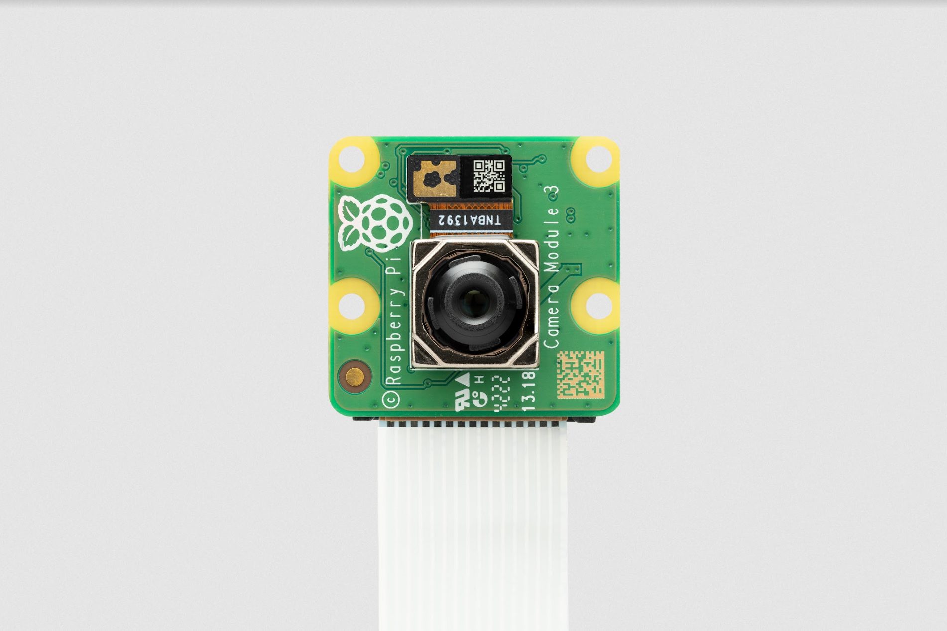
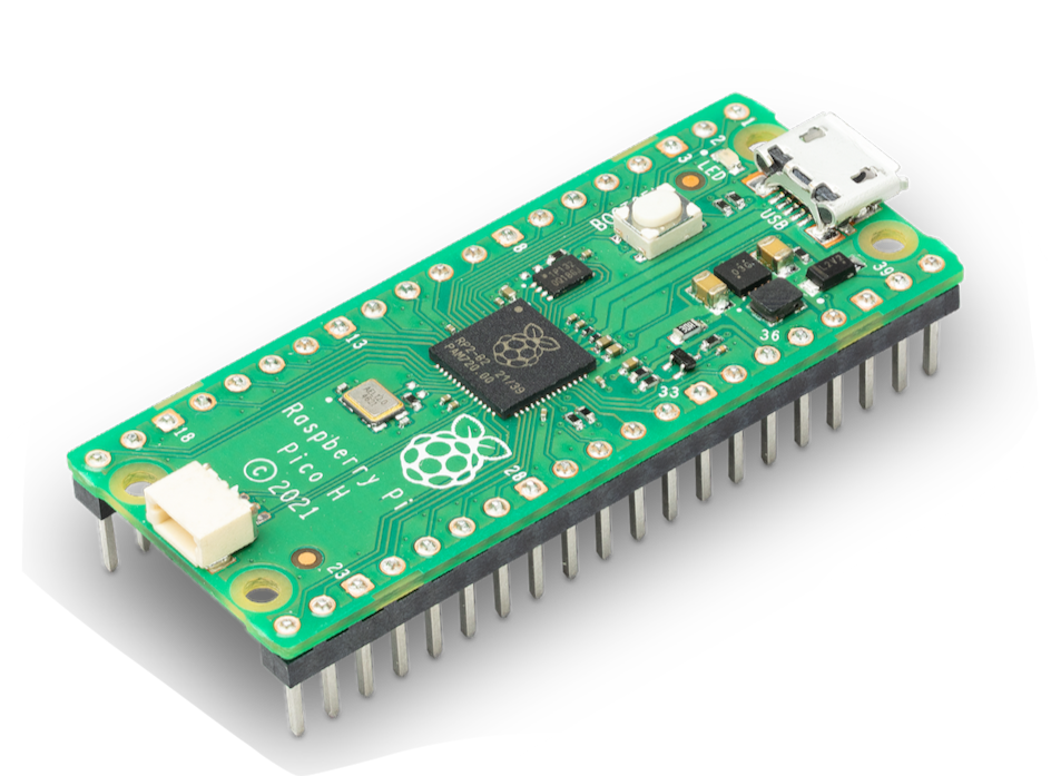
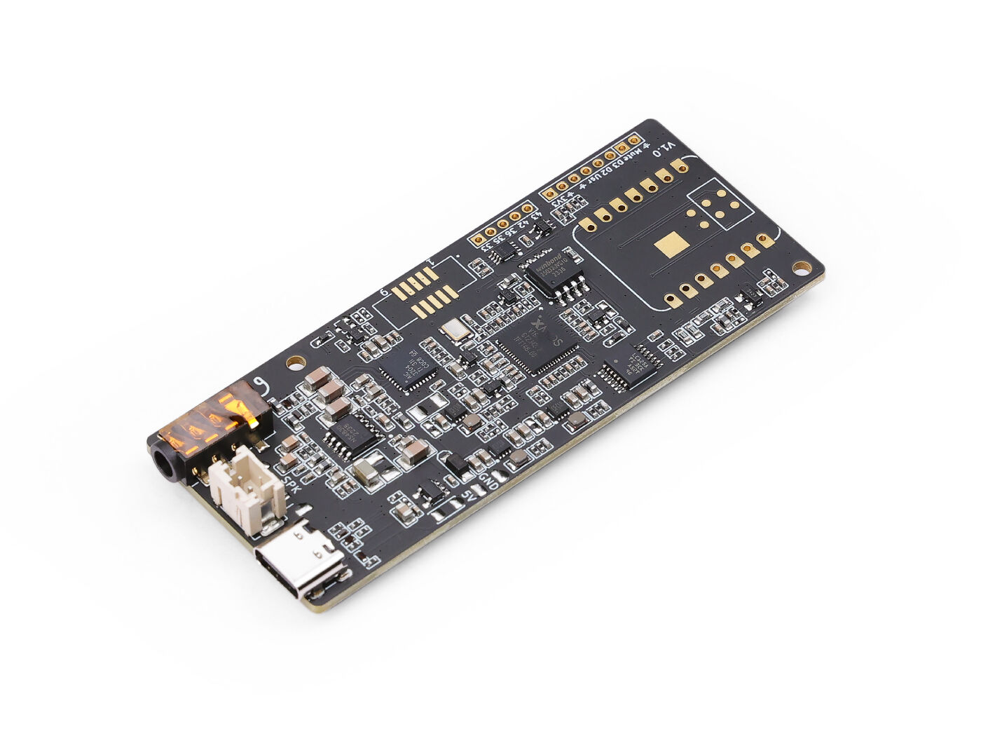
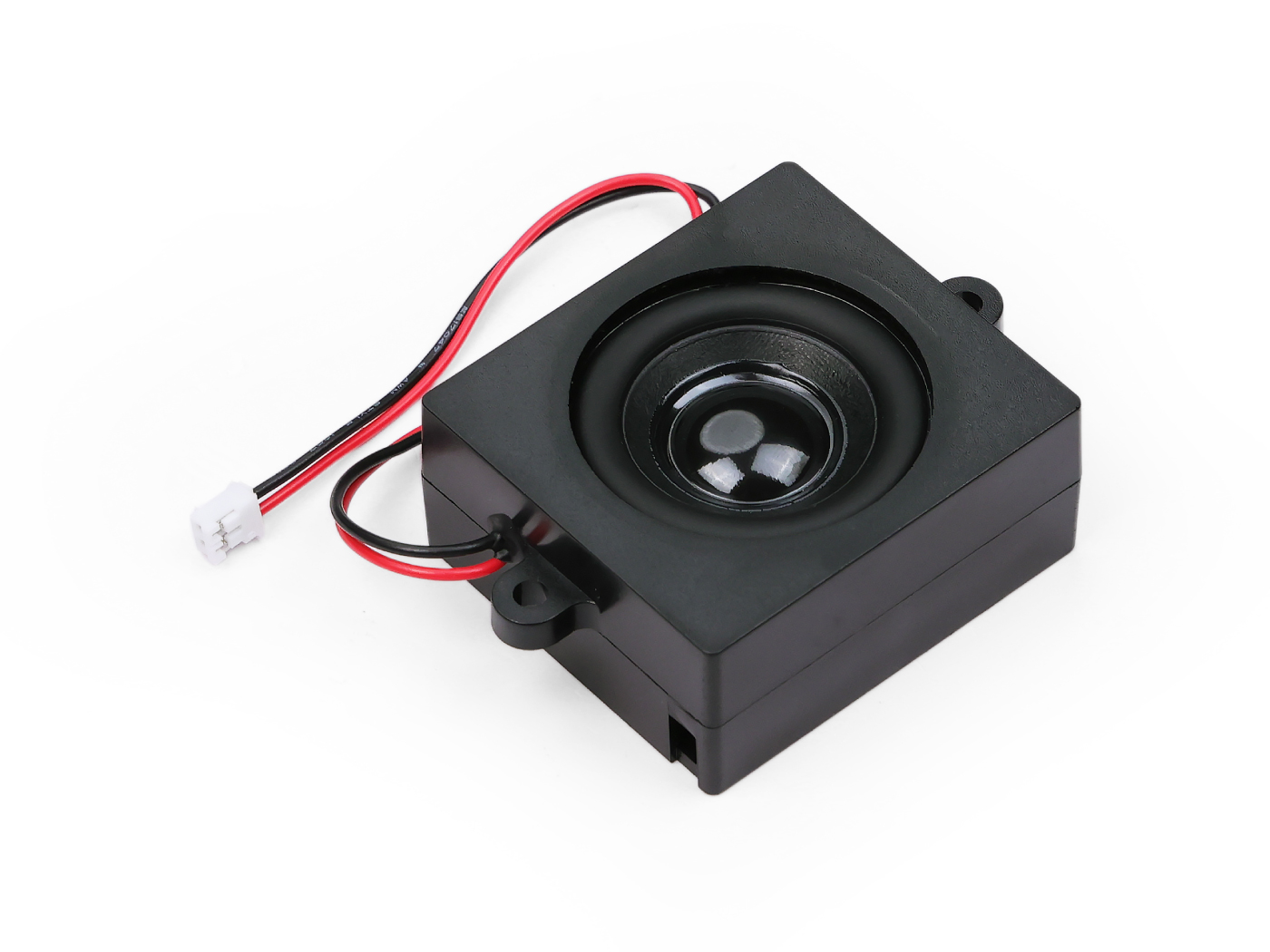
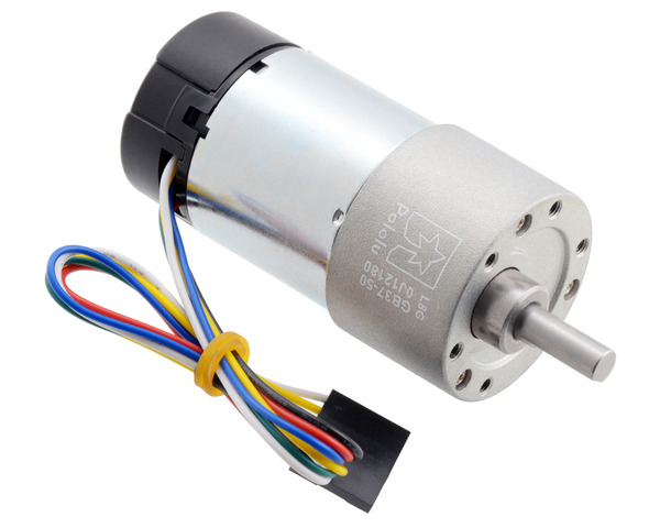
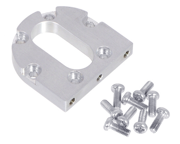
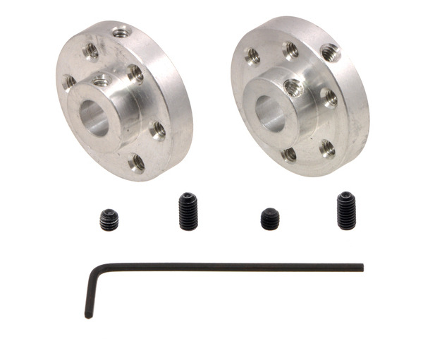
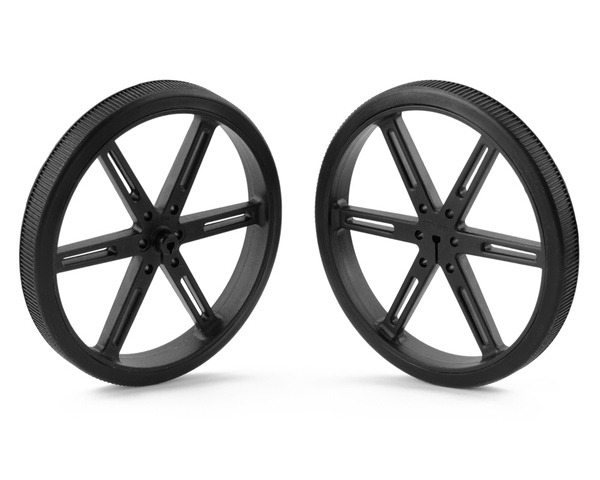
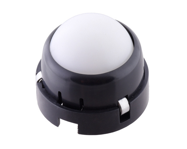
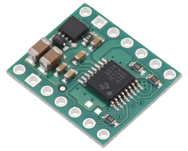
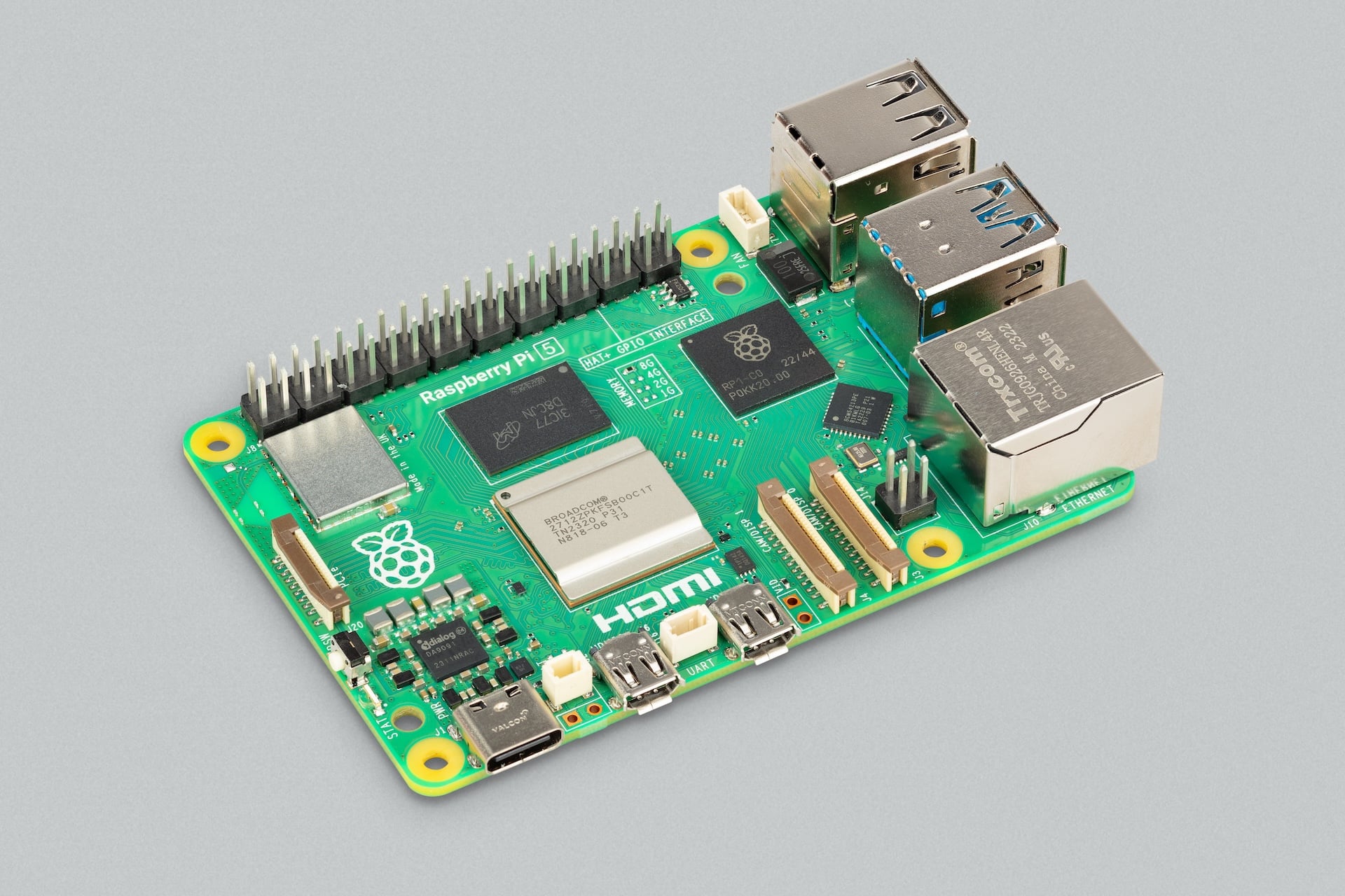
Camera Module 3 StandardSees requested scenes · front-view left carrier with shutterManufacturer photograph · Raspberry Pi LtdReference hardware, not a built MORLOK photographRaspberry Pi 5Runs Linux, camera, audio and network · removable rear trayManufacturer photograph · Raspberry Pi LtdReference hardware, not a built MORLOK photographOriginal Pico HEnforces local motion limits · separate controller trayManufacturer photograph · Raspberry Pi LtdReference hardware, not a built MORLOK photographUSB-only reSpeaker LiteHears speech and processes audio · removable top-front bridgeManufacturer photograph · Seeed StudioReference hardware, not a built MORLOK photographMatched enclosed speakerSpeaks replies · front-view right cassetteManufacturer photograph · Seeed StudioReference hardware, not a built MORLOK photograph4693 encoder motorDrives one wheel with rotation feedback · low on the structural deckManufacturer photograph · Pololu CorporationReference hardware, not a built MORLOK photograph1995 bracket and included screwsSupports a motor · bolted to the metal deckManufacturer photograph · Pololu CorporationReference hardware, not a built MORLOK photograph6 mm shaft hubsConnects a 6 mm shaft to a wheel · one per sideManufacturer photograph · Pololu CorporationReference hardware, not a built MORLOK photograph90 mm wheel pairRolls the mobile base · one per driven sideManufacturer photograph · Pololu CorporationReference hardware, not a built MORLOK photographFront support casterSupports the front of the mobile base · measured deck spacerManufacturer photograph · Pololu CorporationReference hardware, not a built MORLOK photographOne motor driver per channelControls one motor channel · separate controller trayManufacturer photograph · Pololu CorporationReference hardware, not a built MORLOK photograph
0
Start with unpowered work
Inventory and measure
Keep supplies disconnected. Identify what you own before ordering or changing it.
Photograph every board front and back, its model label, connectors and supplied accessories. Record each quantity and condition.
The Pi 5 CanaKit and AD5X are owned. Read the actual supply, cooler, storage, nozzle and filament labels. The robot-car kit is owned, but none of its individual parts is automatically compatible.
Bag fasteners by diameter and length. Label damaged, unidentified and missing items separately. Preserve the original working Pi card and original CAD/software files.
Actual manufacturer photograph · Raspberry Pi Ltd. Confirm the received revision.
Before you start
Set out a tray for each subsystem: computer, camera, audio, mechanical parts and future motor power.
Hands-on detail
Read the printed model identifier rather than identifying a board by colour. Put the label photograph next to its register entry. Count loose spacers separately from installed spacers.
If it does not work: A kit looks similar but its label differs
Keep it in the unidentified tray. Compare its manufacturer drawing and electrical rating before crediting it against the shopping list.
Keep this evidence
Photographs of labels, contents and any damage; a quantity for every owned item.
Finish with
You have dated labels, counts and photographs. No unknown item has been credited as compatible.
Stop if / hold point
Stop for a damaged or unidentified critical part; do not connect it to discover what it is.
Check the caliper zero. Measure critical widths, hole spacings and thicknesses three times in millimetres and retain all readings.
Measure the whole installed envelope: board plus plug, cooler, standoff, cable bend and the space needed to remove it. A bare-board size is insufficient.
Weigh the actual components. Keep measured mass, estimated mass and unallocated payload reserve in separate columns.
Actual manufacturer photograph · Raspberry Pi Ltd. Confirm the received revision.
Before you start
Use a zeroed caliper, ruler, paper and the manufacturer drawing. Keep electronics unpowered.
Hands-on detail
Measure opposite outside faces without squeezing the board. For hole pitch, measure the same edge on both holes, or measure outside-to-outside and subtract one hole diameter. Repeat three times. Also measure plugs while inserted into an unpowered board.
If it does not work: Measured size differs from the CAD reference
Record the actual revision and all readings. Change the candidate interface before printing a fitted mount; do not force the component into nominal geometry.
Keep this evidence
Width, height, thickness, hole pitch, connector projection and cable service envelope in millimetres.
Finish with
Every critical interface has a measurement and a source drawing.
Stop if / hold point
Never drill from a concept image or assume a nominal dimension is a clearance fit.
Mark FRONT on paper. Viewed from the front, put the camera on the left and the speaker on the right; place the microphone bridge at the top-front.
Put the Pi on a serviceable rear tray with cooling and antenna clearance. Reserve a separate controller/driver tray and a low future battery location.
Use measured cardboard envelopes and draw plug-removal paths. Keep microphones away from speaker vibration and fan exhaust. Keep the future stop reachable without crossing a wheel.
Lift each paper module out in the proposed service direction. A lid must be supported independently rather than hang from cables.
Generated visualization based on the candidate design; not a photograph of a built robot or a dimensioned fabrication drawing.
Before you start
Make a full-size paper footprint and label the viewing direction FRONT.
Hands-on detail
Place component envelopes first, then mark the route each cable takes and the path needed to remove each board. The two drive wheels sit outside the later structural deck; a front support caster carries the third contact point. They are purchased hardware, not missing printable shell pieces.
If it does not work: A plug can enter but cannot be removed after the lid closes
Move the module or enlarge the service envelope on paper. Do not commit deck holes while access is unresolved.
Keep this evidence
An overhead layout photo and one side view showing wheel, caster and ground-clearance reservations.
Finish with
All modules, tools and cables have a believable removal path.
Stop if / hold point
The 280 × 220 mm deck is a provisional reference; no new hole pattern or fitted adapter is released.
Use the shopping page to compare exact models and included contents. Select one audio path, not both alternatives.
Record hardware identifiers and the planned software versions. Keep the original manuals and MP1 snapshot alongside the new MP2 register.
For a later motor build, keep 4693 and 4755 branches distinct. The Pico harness and its matching GP10/GP11 firmware truth table must be selected together.
Actual manufacturer photograph · Seeed Studio. Confirm the received revision.
Before you start
Use the exact next-stage register rather than ordering every possible upgrade.
Hands-on detail
For the first bench, identify the Pi 5 supply and cooler, Camera Module 3 Standard, correct Pi 5 camera cable, USB-only reSpeaker Lite and matched enclosed speaker. Keep alternatives in a separate column.
If it does not work: A listing has a matching name but conflicting contents
Hold that purchase. Compare SKU, board revision, supplied cables and seller offer. A bundle photograph alone does not establish compatibility.
Keep this evidence
One chosen model per interface and a list of unresolved measurements.
Finish with
The next purchase and test have an exact configuration and a written stop condition.
Stop if / hold point
A purchase review is not permission to print, flash or energize hardware.
1
Conditional bench procedure
Build the stationary interaction bench
Start with the owned stationary Pi supply after its identity and safe-use checks. Traction remains physically disconnected. These are commissioning instructions for a separately approved session, not results already achieved.
With power removed, inspect the reSpeaker Lite label: USB-only SKU 107990273, without XIAO. Confirm the two microphone openings are clear.
Check the matched 4 Ω 5 W speaker connector and polarity against the received board and documentation before seating it. Do not adapt a plug by force.
Connect one data-capable USB-A to USB-C cable to the Pi. Position its reachable disconnect outside the future shell, label it AUDIO OFF, and provide strain relief without loading the connector.
Do not add an auxiliary 5 V or radio path. This sole USB connection is the proposed physical audio isolation point, and unplugging it also disables the speaker.
Actual manufacturer photograph · Seeed Studio. Confirm the received revision.
Before you start
Place the audio board and speaker on a nonconductive surface, with the Pi supply disconnected.
Hands-on detail
Inspect the speaker connector against the received board documentation. Seat the matched connector squarely without pulling its leads. Route the single USB data/power cable so its disconnect remains reachable and cannot tug the board. Label that point AUDIO OFF.
If it does not work: The USB board does not appear, or the cable only supplies power
Test a known data-capable cable and a suitable Pi USB port. Do not add a second power path as a workaround; it would invalidate the single-disconnect privacy test.
Keep this evidence
A photograph of the complete unpowered connection path, with both microphone openings unobstructed.
Finish with
Exact board, speaker, cable and single power/data path are recorded.
Stop if / hold point
If the received bundle differs, the plug/polarity is unclear, or another power/data path exists, stop and revise the privacy design.
Shut down the Pi and remove its supply before touching either camera connector. Keep the lens and ribbon contacts clean; handle the board by its edges.
Use the official Standard–Mini camera cable type: 15-pin camera end to the Pi 5 22-pin mini end. Measure the route before selecting length.
Use the official installation photographs for the exact connector latch and contact orientation. Release the latch evenly, insert the ribbon squarely and fully, then close it without force. The schematic sketch is not a contact-side guide.
Leave a relaxed service loop and verify it is not pinched. Place an opaque temporary cover in front of the lens for bench privacy without touching the autofocus mechanism; the fitted shutter remains a measured custom part.
Actual manufacturer photograph · Raspberry Pi Ltd. Confirm the received revision.
Before you start
Shut the Pi down, remove power and identify both ends of the Standard–Mini camera ribbon.
Hands-on detail
Use the linked official installation photographs to determine contact orientation for the particular connector. Lift its latch evenly, slide the ribbon fully and squarely, then lock it gently. Route a relaxed bend; keep it away from the shutter path.
If it does not work: No camera is detected later
Power down before reseating either end. Recheck correct cable type and contact side, then repeat the device-list test. Never reseat the ribbon on a live board.
Keep this evidence
A close photograph of each latched end before powering on, and a cable route with no pinch point.
Finish with
Ribbon type, orientation, engagement and clearance have been visually checked with power absent.
Stop if / hold point
Stop if a latch is damaged, contacts are skewed, the wrong cable is supplied or the cover touches the lens.
Inventory and back up the current Pi storage before an approved OS change. Use the software architecture section for the selected 64-bit Linux baseline and supported packages.
Identify the USB audio device and camera locally. Test a short, deliberately captured recording and conservative-volume playback before adding a cloud service.
Start push-to-talk half-duplex: capture only during the deliberate request, stop capture, then play the reply. Route speaker playback through the same reSpeaker device for a later echo-reference test.
Keep model access credentials out of source, browser code, screenshots and public files. Credential setup is a separate secure approval step. No command in this guide installs or configures a secret automatically.
Actual manufacturer photograph · Raspberry Pi Ltd. Confirm the received revision.
Before you start
Use the qualified stationary Pi supply and cooling setup. Traction power remains disconnected.
Hands-on detail
Keep an untouched original storage card. Record the OS release and date. Enumerate camera, playback and capture devices before installing the AI application; use the Software page to test one layer at a time.
If it does not work: A device is absent from the local list
Resolve its power, cable, driver or OS support first. Cloud API settings cannot repair an undetected local microphone or camera.
Keep this evidence
OS identity, detected camera name, USB audio identity and saved local test results.
Finish with
Local record/playback and a requested camera image work on the exact software version; failures remain visible.
Stop if / hold point
Do not proceed to cloud audio until local audio, power, privacy and account setup are accepted.
With a test session ready, disconnect the sole audio USB connection. Confirm the device disappears and no captured or buffered audio is uploaded afterward; the speaker should also stop.
Close the opaque camera cover and inspect a locally captured test image for blocked scene content. Reopen it and confirm opening alone does not send an image.
Check that text labels and distinct states explain power, offline/network, listening, camera capture and faults. Do not call a decorative light a privacy indicator.
Reconnect only deliberately. Privacy recovery must not start listening, transmit queued media or arm motion.
Actual manufacturer photograph · Raspberry Pi Ltd. Confirm the received revision.
Before you start
Run local tests with explicit permission to capture sound or a scene.
Hands-on detail
First establish a known working recording and image. Close the opaque shutter and repeat the same camera test; then unplug the single AUDIO OFF cable and confirm both input and output disappear or fail closed. Reconnect and verify recovery.
If it does not work: The lens still sees a scene, or recording continues after AUDIO OFF
Stop the privacy claim. Check shutter coverage, transmitted light, another microphone or a second audio power/data path. Redesign and repeat before conversation.
Keep this evidence
Open/closed image pair plus a note of the audio devices before and after unplugging.
Finish with
Privacy-off behavior and no late upload are recorded, not assumed from a mute icon.
Stop if / hold point
A failed isolation or shutter test blocks cloud interaction until corrected.
Use home Wi-Fi or a phone hotspot with authenticated local access and encrypted outbound API traffic. Do not open router ports to the robot.
Ask one voice question, then one explicitly requested camera question. Only selected necessary audio/images leave the Pi; automatic recording archives and ambient camera uploads are off.
Use a short fixed set of requests and record response time, safe clarifications, errors and API usage. A proposed initial trial is 20 requests with at least 19 correct transcriptions or safe clarifications and zero unintended actions.
Disconnect the network during a benign request. The robot must indicate offline, discard pending action proposals and stay disarmed after reconnection. Offline manual control, if later built, is a separate deliberate mode.
Actual manufacturer photograph · Seeed Studio. Confirm the received revision.
Before you start
Use a stationary bench and one clear request, such as describing a deliberately placed object.
Hands-on detail
Test listening, responding and one requested camera image separately, then together. Record latency and failures. End the session and repeat with the network disconnected to verify a clear offline state rather than uncontrolled retries.
If it does not work: Speech interrupts itself or the speaker is heard as user input
Lower playback level, move the microphone away from the speaker and compare local capture. Keep push-to-talk while acoustic echo performance is unresolved.
Keep this evidence
A short test log of request, expected result, actual result and measured delay.
Finish with
Stationary interaction passes its written privacy, recovery and power checks with the current hardware.
Stop if / hold point
Motion tools remain absent. A model reply does not prove that a physical action occurred.
2
Measurements and print release required
Qualify the shell and visible modules
Preserve the 24-piece shell. Qualify small samples before committing material to the body. Camera, microphone bridge and speaker adapters are additional measured parts.
Verify the installed AD5X nozzle, actual filament and slicer profile. The original 0.4 mm nozzle / 0.20 mm layer trial is only a starting point for that exact setup.
Inspect every layer, brim and support in the slicer; confirm it fits the actual build area. Do not slice the assembly STL.
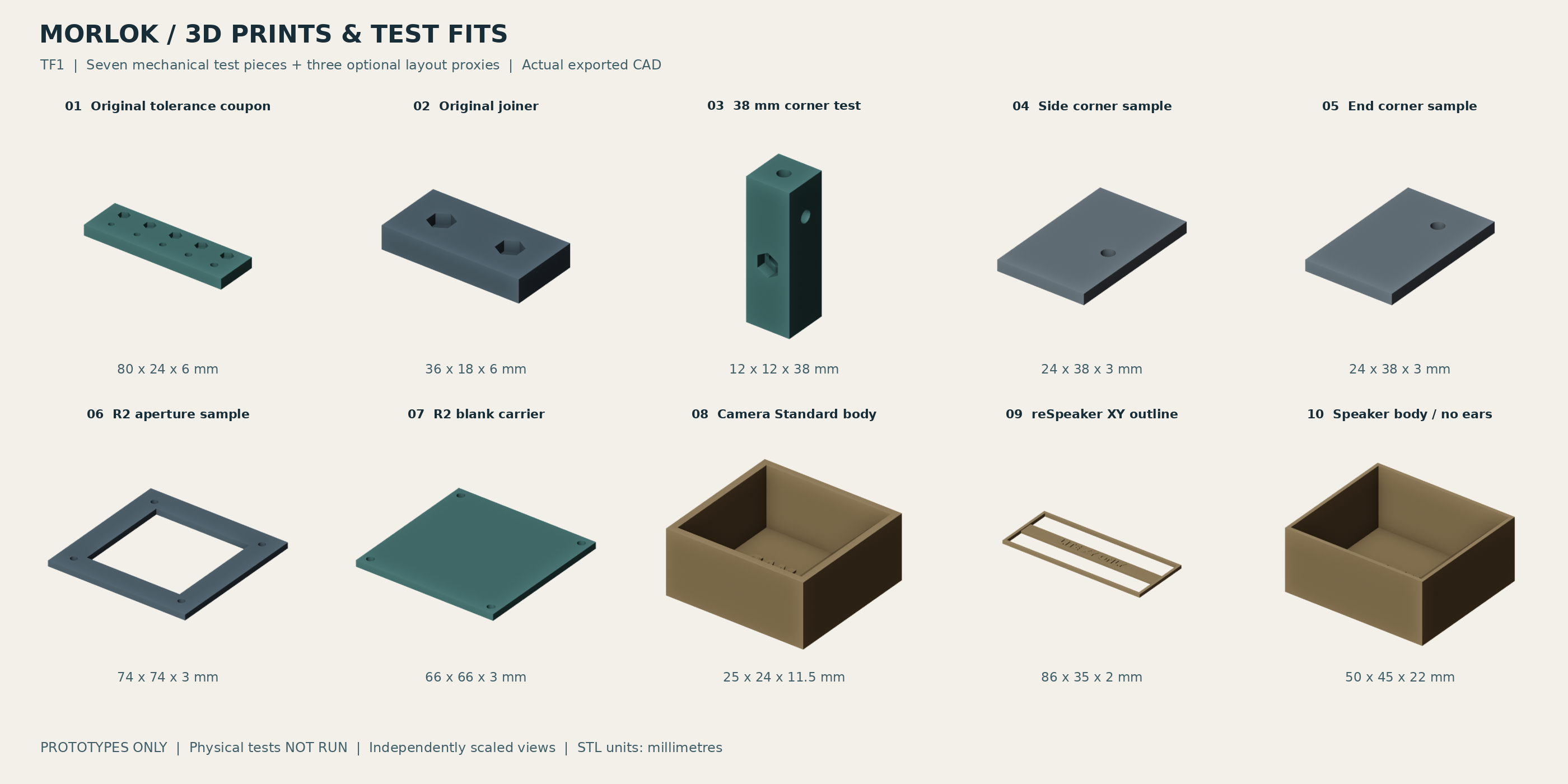
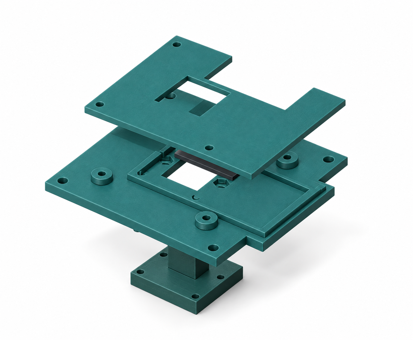
When that exact print is separately approved, print only the original fit coupon. Let it cool, then test actual M3 screws and nut pockets without force.
Record dimensions, material lot, orientation, sliced mass and result. Correct local hole or pocket geometry; do not scale the whole robot to fix a hole.
Actual CAD render of fit-test pieces; not a physical photograph. Use the individual STL files, not this image, for printing.
Before you start
Use the selected print file and confirmed printer/nozzle/material. Keep an unchanged source copy.
Hands-on detail
Import millimetres at 100 percent. Confirm each part touches Z=0. Inspect the first layer, holes, thin features and all overhang layers. Match the physical filament reel at the final handoff; a slicer colour swatch is not proof of the spool route.
If it does not work: The printer dialog still maps the job to a different reel
Do not send. Save a new project copy, reconcile the device filament list and reslice if assignments change. Confirm the final route before one submission.
Keep this evidence
Saved sliced project, profile/version, material, reel mapping and photographed cooled test piece.
Finish with
Cooled coupon fit is recorded. Total filament demand comes from accepted slice masses plus planned waste.
Stop if / hold point
A one-kilogram test spool is not a verified whole-robot material quantity.
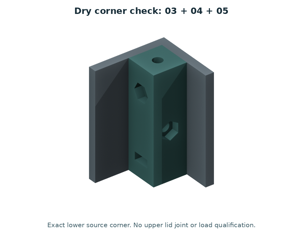
Qualify one joiner, one correct handed post and a side/end/lid corner. Keep the other original CAD revisions intact.
Start each screw by hand with the correct driver. If it binds, back out and inspect alignment; never use power to force a thread into a printed part.
Remove and refit the corner ten times, then inspect after an overnight assembled period for cracks, creep and loose retention.
Only after acceptance, release small batches. R1 has 4 sides + 4 ends + 4 lids + 8 joiners + 4 handed posts = 24 assembly pieces. R2 replaces two front end pieces; do not add them to make 26.
Actual CAD render of the corner test assembly; not a physical photograph. Use the individual STL files, not this image, for printing.
Before you start
Use a local corner sample before committing the complete shell.
Hands-on detail
Clean only loose support or brim. Bring mating faces together without fasteners first, then add the specified fastener by hand. Inspect seams against a flat surface. Record any gap before changing the model.
If it does not work: The joint only closes when a screw bends the wall
Stop tightening. Check warp, elephant foot and dimensional error. Adjust the test interface rather than using clamp force to conceal poor fit.
Keep this evidence
Measured seam gap and a photograph of the joint before and after light fastening.
Finish with
A representative corner and its actual fasteners pass repeated service.
Stop if / hold point
Do not substitute the duplicate generic post for one of the four handed corners.
12
Fit the camera carrier and shutter
Parts and tools for this step
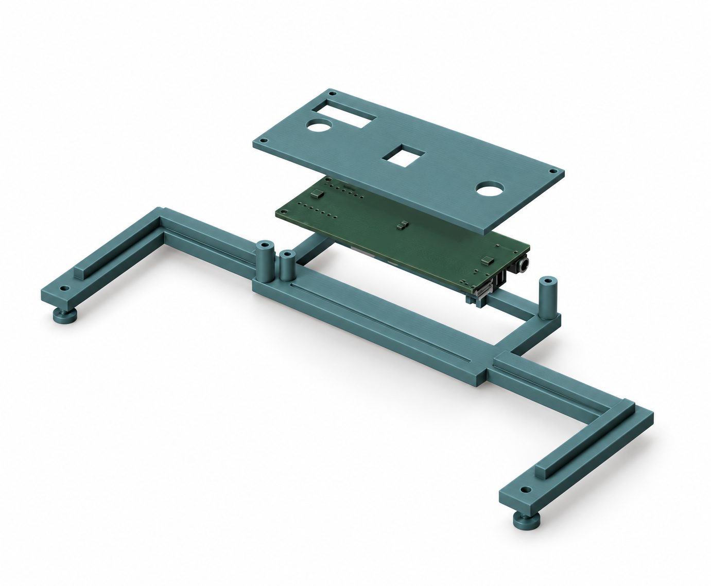
PC1 mechanism trial: C01 ×1, C02 ×1, C03 ×1; four M2 bolts and four matching nuts. Bolt length remains measurement-dependent. The camera and C04 spacers are not needed for this first unpowered trial.
Identify C01 carrier, C02 retainer and C03 slider from the PC1 package. Keep the old R2 blank carrier as a historical interface sample; it is not the new camera mechanism.
First assemble the three printed pieces without electronics. Clean loose brim, check flatness and place the slider in the channel with its grip accessible. Align the retainer and confirm the moving surfaces are free of debris.
For a retained mechanism test, use four M2 bolts and nuts with length selected from the measured stack. The nominal plastic stack is 6.6 mm, before real washer/nut engagement. Tighten evenly and confirm the full 24 mm design stroke without force.
Only after that trial passes, qualify the actual camera, four C04 spacers, lens clearance, ribbon route and optical shutter coverage. Camera mounting and R2 shell attachment are separate fastener interfaces. The optional ring light is not part of this assembly.
Generated visualization based on PC1 CAD. Includes reference electronics for context; the first trial prints only C01, C02 and C03. Original CAD controls exact geometry.
Before you start
Start with one C01 carrier, one C02 retainer and one C03 slider. No camera is needed for the first mechanism test.
Hands-on detail
Let parts cool, inspect flatness, and remove brim without rounding sliding edges. Place the blade in the carrier channel with its grip accessible; align the retainer without trapping it. Four M2 bolts/nuts are required for a retained test; select length from the actual 6.6 mm nominal plastic stack plus real nut/washer engagement. Tighten gradually and evenly. Check the entire 24 mm design stroke by hand.
If it does not work: The blade binds only after the retainer is tightened
Back off and inspect flatness, debris and captured thickness clearance. Do not lubricate near optics or force the blade. Record the interference location for a CAD correction.
Keep this evidence
A full-stroke video and measured stack/bolt length. This does not validate camera fit, lens clearance or optical opacity.
Finish with
A removable camera module and shutter pass measured fit and privacy tests.
Stop if / hold point
The reference interface dimensions do not release the new camera holes or sliding clearances.
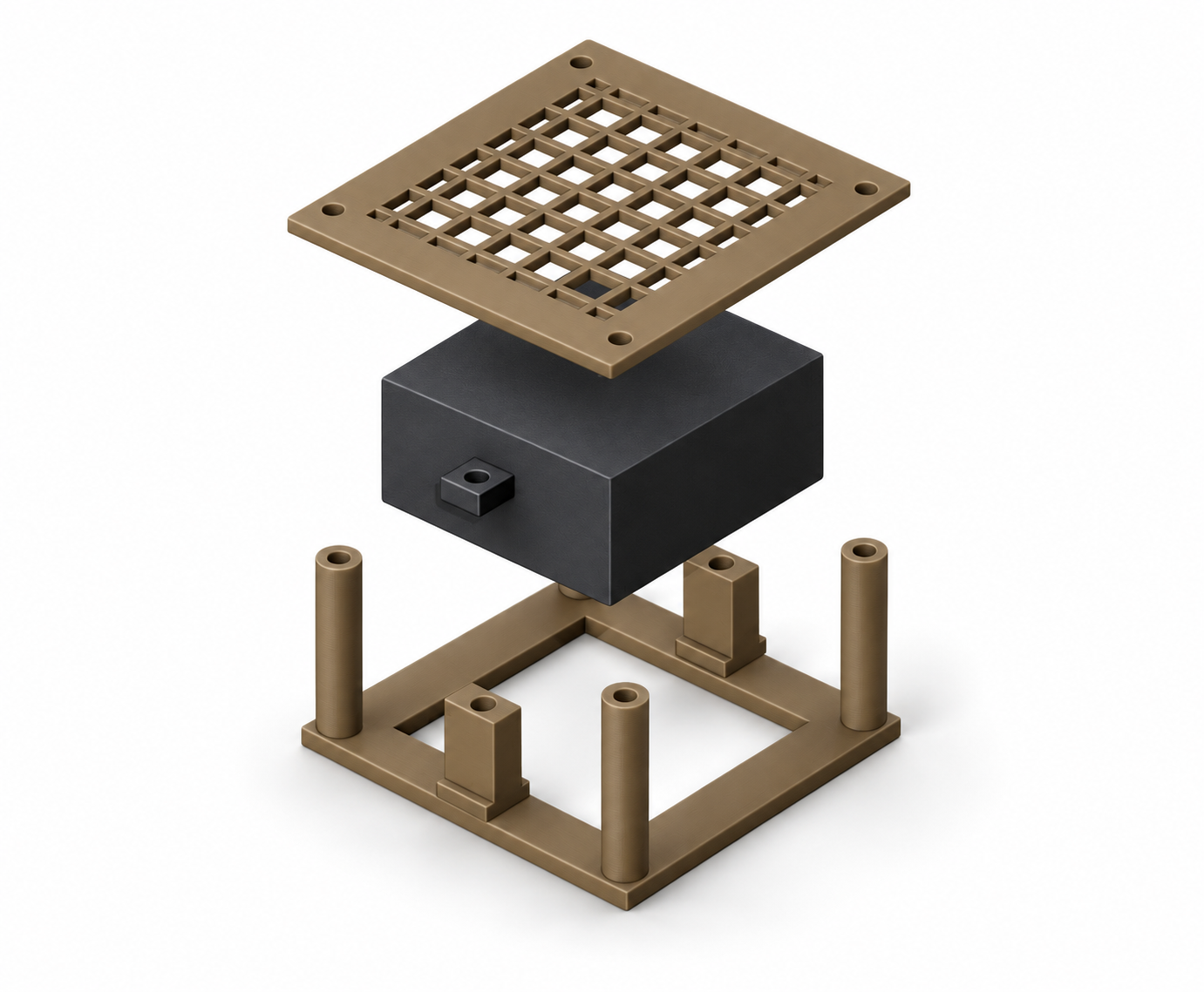
Identify S01 speaker cassette and S02 grille, plus M01 microphone bridge, M02 guard and two M03 spacers. Compare each received component to the PC1 reference before fitting.
The speaker remains in front of the shell aperture and is supported at its documented mounting ears. Check real ear thickness, cone/grille clearance, connector body and lead bend; the catalogue body size alone is insufficient.
Check the received reSpeaker Lite revision against the reference STEP model. The manufacturer nominal outline and model differ; do not force an unmeasured board into the bridge. Keep microphone openings and USB access clear.
After accepted dry fit, repeat open-bench and enclosed audio tests at conservative volume. Do not use the bridge as a handle. Physical acoustics, load capacity and privacy behaviour are still unqualified.
Generated visualization based on the candidate design; not a photograph of a built robot or a dimensioned fabrication drawing.
Before you start
Compare the received speaker and Lite board with the reference drawing before fitting their carriers.
Hands-on detail
Fit the speaker by its mounting ears, not by compressing its cone or enclosure. Check grille clearance, lead exit and access to the connector. For the microphone bridge, compare board revision and hole pattern; keep both microphones and USB access clear. Test acoustics open on the bench before closing the shell.
If it does not work: The speaker rattles or speech capture worsens when enclosed
Compare with the open-bench result. Check contact with grille, loose fasteners, fan noise and speaker-to-microphone vibration. Do not hide the issue by increasing volume.
Keep this evidence
Open-versus-enclosed audio comparison, actual gasket choice, lead clearance and board revision.
Finish with
Mic ports, grille, USB disconnect and fasteners remain accessible and serviceable.
Stop if / hold point
Do not stretch original panels or invent a mic-only switch to make a render fit.
Install electronics only on an accepted tray and appropriate insulating standoffs. Inspect underneath for screw tips, conductive debris and trapped cables.
Support the lid separately while opening it. Label matching cable ends and give plugs a removal path and strain relief.
With power isolated, remove and refit one module using normal tools without cutting wiring or dismantling unrelated assemblies.
Repeat matching open-body and closed-body workloads after approved commissioning, logging temperature, throttling, audio, image obstruction and Wi-Fi behavior.
Generated visualization based on the candidate design; not a photograph of a built robot or a dimensioned fabrication drawing.
Before you start
Disconnect supplies and lay out the module fasteners in labelled groups.
Hands-on detail
Rehearse removing the Pi, camera cable, speaker and audio board in turn. Support the lid independently; disconnect accessible plugs before lifting a module. Keep cooling and antenna space clear. The microphone bridge is not a carrying handle.
If it does not work: A service operation requires pulling a cable or loading the bridge
Change the access path or strain relief before final assembly. Do not make a fragile assembly the only way to open the robot.
Keep this evidence
A removal sequence with tool access and cable slack checked for every module.
Finish with
Ten service cycles and closed-body regression results are attached for the exact geometry.
Stop if / hold point
A cosmetic panel must never carry a heavy battery or hide the drive stop.
3
Later stage after configuration review
Prepare the unpowered rolling base
This stage is separate from the useful stationary robot. Candidate parts and sketches do not release drilling, load capacity or traction power.
Overlay the actual motors, brackets, hubs, wheels, caster, posts, battery and trays on the full-size deck layout.
Include wheel overhang, ground clearance, screw access and the low restrained battery. Check the three-contact support triangle and actual component masses.
Have the drawing, material, hole map and support/load assumptions reviewed before cutting or drilling. The 3 kg goal and 4 kg screening envelope are not load ratings.
Actual manufacturer photograph · Pololu Corporation. Confirm the received revision.
Before you start
This is a design hold point for the later mobile base. Keep the interaction bench stationary.
Hands-on detail
Reconcile the metal deck drawing, motor bracket holes, wheel clearance, caster height, battery restraint and centre of mass using measured parts. The shell is not a substitute for a qualified structural deck.
If it does not work: The wheel rubs the shell or caster height tilts the deck
Revise the measured layout and spacers. Do not drill a guessed hole or accept a tilted frame because the screws fit.
Keep this evidence
A reviewed dimensioned deck drawing and hardware schedule before fabrication.
Finish with
A dimensioned, reviewed drawing and mass/load record exist.
Stop if / hold point
No released deck drawing is currently supplied; do not machine from this page.
After fabrication approval, clamp and deburr the bare metal work with electronics absent and suitable eye protection. Remove all swarf before assembly.
Fit one 4693 motor to each 1995 bracket using its verified supplied face screws. Confirm the actual stack and manufacturer engagement limit before tightening.
For this 37D reference, screw penetration into the motor face must not exceed 3 mm. Compute penetration as under-head screw length minus the clamped bracket/washer stack.
Use separate reviewed deck fasteners. Align brackets squarely and tighten with an appropriate hand tool; no universal torque is invented here.
Actual manufacturer photograph · Pololu Corporation. Confirm the received revision.
Before you start
Use the selected motor branch and its matched bracket drawing; motor power stays absent.
Hands-on detail
Lay each motor beside its bracket and verify bolt pattern and permitted screw intrusion against the exact motor data. Start screws by hand, distribute seating evenly and keep encoder terminals free of contact. Final torque must come from qualified hardware guidance.
If it does not work: A screw bottoms out before the bracket seats
Stop. Measure engagement and check the correct screw length; washers are not a substitute for an unreviewed stack.
Keep this evidence
Exact motor part number, bracket identity and measured engagement record.
Finish with
Two mechanically aligned motor/bracket assemblies have verified screw engagement.
Stop if / hold point
Stop for binding shafts, bent hardware, uncertain screw length or an unsupported deck pattern.
Use the two 6 mm hubs from one 1999 pack and the two wheels from one 1435 pack. Do not buy two packs because there are two sides.
Place the hub on the intended shaft flat without hammering or forcing the gearbox axially. Use the supplied set screws and correct hex tool.
Attach each wheel with the separately specified M3 wheel screws. Pololu documents that the 1435 mounting holes accept M3 or #4 screws; actual screw length and clearance still require measurement.
Turn each wheel by hand with power absent. Check wobble, rubbing, fastener retention and full clearance.
Actual manufacturer photograph · Pololu Corporation. Confirm the received revision.
Before you start
Use two matched 6 mm hubs and two compatible wheels; count the pair only once.
Hands-on detail
Dry-fit the shaft/hub connection, align the set screw with the specified shaft feature, and verify the wheel mounting pattern. Turn the wheel by hand to inspect rubbing and visible wobble before any powered test. Preserve access to the set screw.
If it does not work: The hub slides poorly or wheel runs visibly out of true
Do not hammer or power through it. Check shaft diameter, burrs, seating and bolt pattern against the exact products.
Keep this evidence
A manual rotation video and clearance measurements on both sides.
Finish with
Both wheels rotate freely and their hub/fastener stack is recorded.
Stop if / hold point
Do not confuse hub set screws with wheel attachment screws or drill the native wheel centre as a shaft adapter.
One pack contains two hubsConnects a 6 mm shaft to a wheel · one per sideManufacturer photograph · Pololu CorporationReference hardware, not a built MORLOK photographOne pair contains two wheelsRolls the mobile base · one per driven sideManufacturer photograph · Pololu CorporationReference hardware, not a built MORLOK photograph
Set caster spacer height from the actual axle and deck geometry. Check the complete caster envelope, ground clearance and level deck under representative load.
Use a disconnected mass dummy while developing the battery cradle. Positive stops and a retained strap must attach to the structural deck.
Only after the source is identified, handle the actual pack according to its maker instructions with protected terminals and a clear removal path.
Reweigh all-up mass and the three support reactions. If shaft loading or stability is unsupported, revise support or reduce mass before proceeding.
Actual manufacturer photograph · Pololu Corporation. Confirm the received revision.
Before you start
Keep the battery electrically disconnected; use a measured mass/envelope for layout if the pack is not selected.
Hands-on detail
Check the caster mounting pattern and required spacer using the deck drawing. Verify all intended contact points meet a flat surface. Reserve restrained battery space away from sharp fasteners and moving wheels; maintain connector and inspection access.
If it does not work: The pack fits only by compressing cables or losing stop access
Revise the layout. A loose pack, strap across exposed contacts or inaccessible disconnect is not an acceptable workaround.
The base is stable and serviceable with recorded loads, still unpowered.
Stop if / hold point
Do not lift the robot by its shell, sensor bridge or wheels; a loose battery blocks progress.
4
STOP until reviewed engineering exists
Close electrical and software release gates
The following sections explain the sequence and required evidence. They deliberately do not provide a guessed motor pinout, fuse value, current setting or energized fault recipe.
Freeze one motor branch, controller, driver backend, source, charger and converter. Review full pack voltage, worst-case current, inrush and all connector/wire ratings together.
Resolve independent drive-energy stop, DC isolation, overload protection, fuses, encoder level conversion and returned-energy handling for full pack, source removal and protection-trip cases.
The two DRV8874 boards require a new reviewed adapter and firmware. The old MDD10A mapping is not a drop-in release. Do not connect 5 V encoder outputs directly to Pico inputs.
A competent reviewer must produce the schematic, mating-face pinout, ratings, instrumented fixture and predeclared test limits before the harness is built.
Actual manufacturer photograph · Pololu Corporation. Confirm the received revision.
Before you start
No motor wiring is released by this guide yet. Gather exact ratings and diagrams first.
Hands-on detail
Review source voltage/current, motor stall demand, driver carrier, returned energy, fuse and conductor ratings, logic levels, local stop and watchdog as one circuit. Keep 4693/4755 and GP10/GP11 variants distinct. Each unresolved value needs an owner and evidence.
If it does not work: Any wire gauge, fuse value, pinout or stop behaviour is unknown
Stop at the design review. Do not use a generic internet robot diagram or infer ratings from wire colour.
Work only from the released pinout and specified wire/contact schedule. Match every connector from its documented mating face, not wire color alone.
Use the contact-specific crimp tooling and pull-test method. Add labels, strain relief and protection where a harness crosses an edge.
With all energy isolated and the correct instrument mode, a competent builder verifies point-to-point continuity, polarity and isolation between different nets.
Record actual findings and inspect the board undersides and exposed terminals. Never use resistance/continuity mode on an energized circuit.
Actual manufacturer photograph · Pololu Corporation. Confirm the received revision.
Before you start
Only begin after the reviewed harness schedule exists; all sources remain disconnected.
Hands-on detail
Label both ends of every lead before routing. Match connector cavity numbers to the released pin table. Inspect crimps, retention, strain relief and abrasion protection. Perform the documented continuity and short checks on the unpowered harness.
If it does not work: Continuity differs from the pin table or a terminal pulls out
Quarantine that harness. Correct and recheck the full affected branch; do not rely on a connector that appears seated.
Keep this evidence
Signed pin-to-pin check record and clear photographs of connector orientation.
Finish with
A checked harness map and G03 inspection record exist.
Stop if / hold point
No final harness schedule exists yet; this is a held procedure, not wiring instructions.
Run the existing simulator on a supported host and keep its revision/results distinct from physical evidence.
In a separately inspected logic-only fixture, the original Pico H remains motor-disabled. Confirm cold-start disarmed behavior and the selected local arm/interlock truth table.
Test malformed, expired, duplicate and out-of-range commands, process exit, lost traffic, reset and watchdog behavior. Reconnect must never re-arm automatically.
The AI may propose bounded high-level intent only. The Pi validates it and the independent controller enforces expiry and limits; first-release software exposes no motion tools.
Actual manufacturer photograph · Raspberry Pi Ltd. Confirm the received revision.
Before you start
Use a configuration matched to the reviewed controller truth table, with motor power disconnected.
Hands-on detail
Exercise command limits, arming rules, stale-command timeout, restart and communications loss using safe simulated outputs. Verify the local controller rejects invalid motion requests independent of the cloud application.
If it does not work: Restart or network loss leaves a previous command active
Fail the test. Correct local state handling before any powered motor trial. A successful conversation is not motion-safety evidence.
Keep this evidence
Versioned firmware/configuration and expected-versus-observed results for every fault test.
Finish with
Fresh simulator and logic-only records identify exact software, configuration and hardware.
Stop if / hold point
GP10 R1 normally-open hold and Bench 3.1 normally-closed interlock with GP11 arm must not be mixed.
The electrical reviewer selects suitable source limiting, voltage/current/temperature instrumentation, mechanical restraint and an independently reachable stop.
Define component-level limits and failure actions before testing. Confirm the fixture remains safe when motor-generated energy appears after the source is removed.
Review one-channel startup, current-limit accuracy, fault interpretation, reset behavior and stop/returned-energy cases. Only then may a separately approved G07 procedure proceed.
Actual manufacturer photograph · Pololu Corporation. Confirm the received revision.
Before you start
The powered test fixture is a separate engineering release, not an ordinary assembly step.
Hands-on detail
Confirm restraint, reachable independent stop, instrumentation, current limits and a safe disconnect method. Review the test with the exact motor/source/driver combination. Start with one channel and no ground contact only after that review passes.
If it does not work: A protection threshold or fixture load is not established
Do not energize. Complete the design and fixture review first.
Keep this evidence
Approved test sheet and instrument/fixture setup photographs.
Finish with
G06 is accepted for one exact staged procedure and fixture.
Stop if / hold point
Do not short a pack, bypass protection or hold a wheel to demonstrate stall current. Beginner trial-and-error cannot close this gate.
5
Future supervised qualification
Measure motion and maintain the accepted robot
No physical test has been run for this revision. A written checklist stays NOT RUN until measured evidence is attached.
After G00/G01/G03/G04/G06 and all fitted-module gates pass, follow the reviewed fixture procedure with wheels clear and rotating parts guarded.
Enable one channel at a time using short bounded low-speed commands. Measure direction/count sign, current, actual speed, stop and returned-energy behavior before testing both together.
Only after G07 acceptance, use a dry level enclosed floor area with direct supervision and physical exclusion of stairs. The 50 mm/s starting candidate is not a measured safe-speed claim.
Measure complete stopping distance for software loss, physical stop and relevant load/source states. Restore of network, power or an interlock must leave motion stopped.
Actual manufacturer photograph · Pololu Corporation. Confirm the received revision.
Before you start
Progress only from passed one-channel and raised-wheel tests with supervision.
Hands-on detail
Verify stop, direction, current and temperature at the reviewed limits. Then move to a clear controlled floor area with conservative speed and a reachable stop. Test communication loss before adding navigation features.
If it does not work: Direction, stopping distance or current differs from the accepted result
Stop and return to the appropriate bench test. Do not compensate with an AI prompt or a faster control loop.
Keep this evidence
Measured results and a specific sign-off for the floor-test configuration.
Finish with
G07 and G08 contain actual logs, measurements and reviewer acceptance.
Stop if / hold point
Do not infer floor stability or stopping distance from free-spinning wheels. No autonomous, outdoor or unattended operation is released.
Repeat the accepted workload with the body fitted. Compare temperature, rail behavior, fan/audio performance, camera view, Wi-Fi and mechanical clearance.
After cooling, inspect fasteners, printed bosses, cable pinch points and restraint. Record a successful remove/refit of each service module.
For each later sensor or payload, write its mounting, voltage/current, connector, data interface, identity and removal contract. Reweigh and repeat affected safety tests.
Keep old revisions and failed results. An upgrade is accepted only after the new matched configuration passes its own evidence gates.
Generated visualization based on the candidate design; not a photograph of a built robot or a dimensioned fabrication drawing.
Before you start
Finish only after each affected subsystem passes its own acceptance checks.
Hands-on detail
Photograph internal routing before closing. Recheck cable pinch points, vent openings, shutter travel and service access. Retest microphone/speaker, camera privacy, network recovery and any approved motion functions after closing the body.
If it does not work: The closed body changes cooling, audio or movement
Reopen and diagnose the affected interface. Keep the prior passing result; do not mark the enclosed configuration passed automatically.
Keep this evidence
As-built photos, revision list, replaced parts and a dated maintenance/test record.
Finish with
G09 and the configuration/service record match the real robot.
Stop if / hold point
Changing wheels, battery, motor, driver, payload or speed requires a new affected release; modular does not mean electrically universal.
Sources and illustration credits
The sequence preserves the original MORLOK BP1, R1/R2 and MP1 project evidence. The interaction-first order and exact two-store sourcing policy are the MP2 revision. Original private project files remain in the Robot Space and are not exposed here.
Line diagrams are original explanatory drawings. Product photographs are credited beside each image and retain the respective manufacturer’s rights. They show reference components, not verified received parts, a completed assembly or measured clearance. No personal presenter media is included.